Week 8 Rube Goldberg
In our Rube Goldberg machine we will combine several circuits
we used in previous weeks to combine a digital display, motor, relay, opamp,
temperature sensor, and a LED to hit a ball off a tee.
In our set up we have our clock sending a signal to our
counter; the then counter is sending a signal to the driver, then the driver
controlling the digital display. The display will continue to count from 0 to
9, once it past 9 it will start over.
 |
| Whole circuit, and setup |
We connected the inputs of a XOR gate to the C and D outputs
of the counter. Then we connect an LED to the output of the XOR gate to show
when the logic gate runs true. The logic gate will run true when the display is
between 4 and 9.
From the truth table and the table of the outputs of the
counter you can see the green LED will be on when the display if between 4 and
9. Between 4 and 9 either the D or C input is high, but never both at the same
time.
 | |
| XOR Gate(7486) Truth Table |
 |
| Truth Table for the counter |
In the picture below you can see that the display is not
between 4 and 9 and the green LED is not on.
 |
| Figure 2: Display 3,green LED not on |
As you can see in the picture below the display is now
between 4 and 9 and the green LED is on.
 |
| Figure 3: Display between 4 and 9, green LED on |
We have a blue LED connected to the normally closed terminal
of the relay, so it will be on when the relay is not engaged.
 |
| Figure 4: Relay not engaged, blue LED on |
We have connected a clear LED to the normally open terminal
of the relay to show when the relay is engaged for testing. When we engage the
relay you can see the clear LED come on and the blue LED go off. In the photo
we manually changed the relay by applying 6 volts to the solenoid for testing
purposes.
 |
| Figure 5: Relay engaged, blue LED off, and clear LED on |
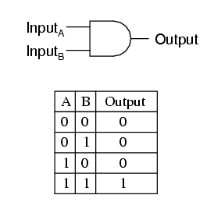
We now have connected the output of the XOR gate and the
output of the normally closed terminal of the relay to a AND gate. The output
out of the AND gate is connected to the yellow LED light to represent out motor.
Following the truth table for the AND gate below you can see that the yellow
LED will turn on when both the relay and the XOR gate run true.
 |
| AND Gate (7408) Truth Table |
In the photo below you can see clear LED is on showing that
the relay is engaged, but the green light is not on showing that the XOR gate
is now true. Which doesn’t turn on the yellow LED.
 |
| Figure 6: Relay engaged, clear LED on, green and yellow LED off |
Now when the display is between 4 and 9 the green LED turns
on, this make the logic for the and gate run true turning on the yellow LED.
 |
| Figure 7: Relay engaged, display between 4 and 9, green, clear and yellow light on. |
We connected the temperature sensor to the op-amp in a
non-inventing configuration. Then the amplified signal will go to the solenoid
of the relay. When the temperature sensor is heated with the blow dryer it will
engage the relay.
In the video below you will see
the whole circuit in motion. The display will repeatedly count from 0 to 9, the
Green LED will be on from 4 to 9 on the display, the relay will engage when the
temperature sensor is warm enough, the motor will spin once the green LED is on
and the relay are both engaged. The motor will then send the ping pong ball
flying.
Problems we had
We first notice that the display was counting too fast for
our setup, so we had to reconfigure the set up of the resistors on the clock to
slow the clock speed down. We increased Ra from 150k ohms to 330 ohms. Then we
increase Rb to 820k ohms. Below you can see out clock set up.
We had an issue with the AND gate
running true with only one input of 1, from the truth table of an AND gate we
know this is not right. We found that the one input of the AND gate that was
not one need to be ground to the AND gate to function properly. So we ground
the inputs, but this caused and issue since electricity is lazy and flowed the
path of least resistance and with the inputs grounded the signals coming from
the relay and the XOR gate would go straight to ground. So we instead of
directly grounding the inputs we used a 1k ohm resistor to ground them. This
then forced the signals to go to the AND
gate and not straight to ground.
The last issue we had was that we
found the output of the AND gate was not strong enough to power the motor. So
we thought about the first time we built a Rube Goldberg circuit with a
transistor and the light sensor. We used the same set up but replaced the
photocell and the 5 v supply with the output of the AND gate, thus allowing us
to turn the motor with an AND gate.
I like how you guys propped up your DC motor. We didn't really think of anything for ours, but now we know in the future that we need to prop it up somehow. It was also a nice touch briefly explaining what you guys did in each picture and how you went about solving your issues.
ReplyDeleteThanks! :)
DeleteLike the setup! The circuit looks nice and easy to see how you set up everything. Lets hit the golf course!
ReplyDelete